Hydraulic (grey) measures
Hydraulic (grey) measures aim to prevent floodwaters from reaching residents and infrastructure through construction of structures or pumps. More natural measures to prevent flooding are described in the section on urban green infrastructure. FloodAdapt can simulate two main types of hydraulic (grey) measures: floodwalls and levees and pumps. This section describes how these measures can be specified in FloodAdapt and how they are represented in the modeling.
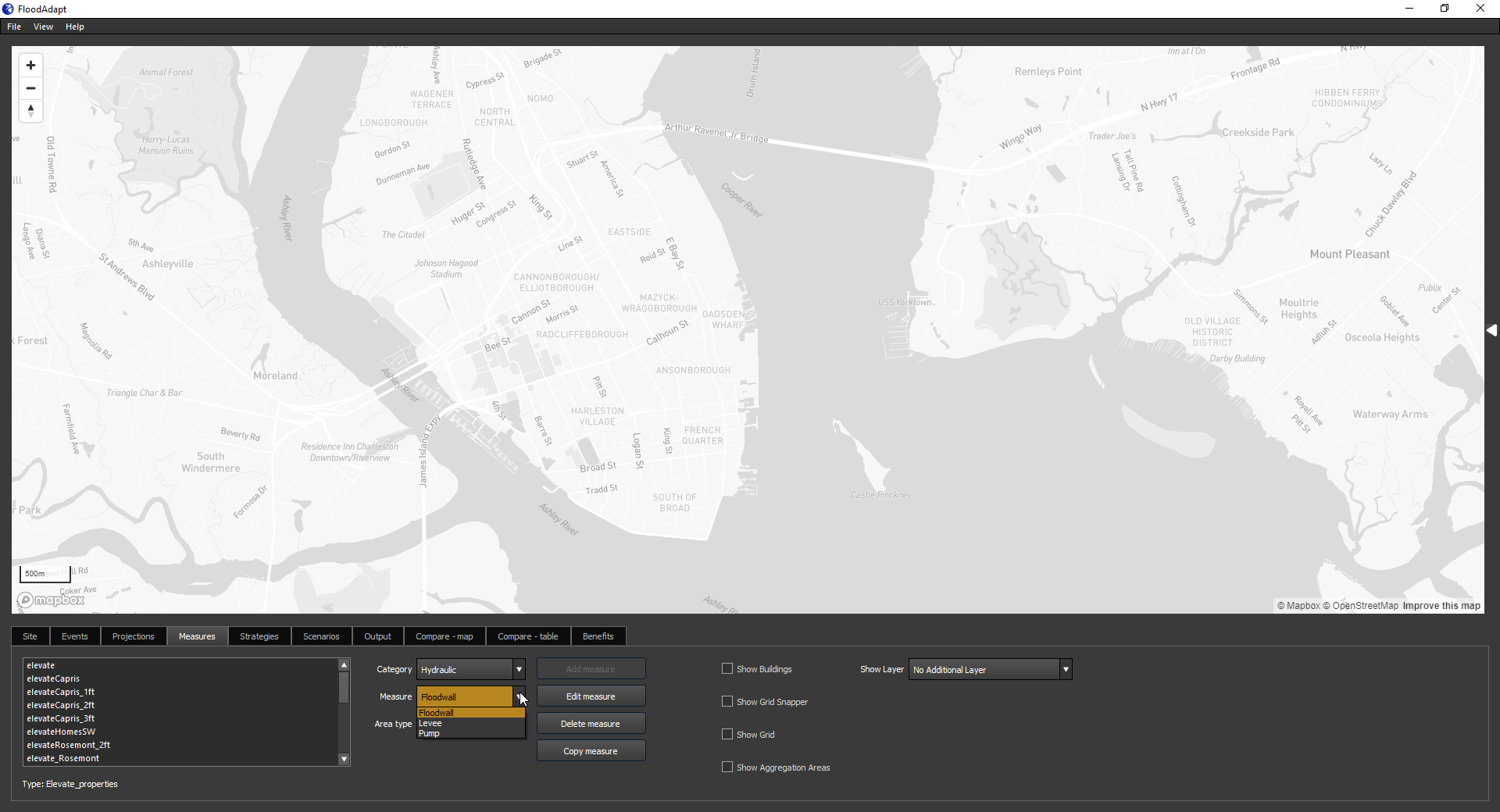
To specify a hydraulic measure, the user goes to the Measures tab, and in the “Category” drop-down menu selects “Hydraulic” (see Figure 2). The user can then choose for “Measure” one of the measure types: floodwall or levee, or pumps. For each of these measures, the user will choose an “Area type”. This indicates how the user will specify the location of the measure. There are two options:
Draw polyline: this option allows a user to click a polyline in the map to represent either the floodwall/levee or the intake/outtake location of a pump
Import polyline: this option allows a user to import a polyline that they have made externally, for example in GIS software
When specifying a hydraulic measure, it is useful to see the underlying hazard model grid which helps understand how the measure will be schematized in the model (hydraulic measures are always snapped to the hazard model grid). For this the user can click the “Show Grid” box. In addition, if you click the “Show Grid Snapper” box, FloodAdapt will show you how your polyline will be snapped to the hazard model grid. This is especially important when drawing a floodwall or leveel to make sure that the area you want to protect is well-represented once the polyline is snapped to the grid.
Floodwalls and levees
Floodwalls and levees are engineered structures designed to provide barriers against flood waters, thereby mitigating flood risks and protecting vulnerable areas from inundation. To implement floodwalls or levees in FloodAdapt:
- Go to the Measures tab
- Select “Hydraulic” for the Category
- From the Measure drop-down menu, Select “Floowall” or “Levee”
- Select one of the “Area type” options and then click “Add Measure”.
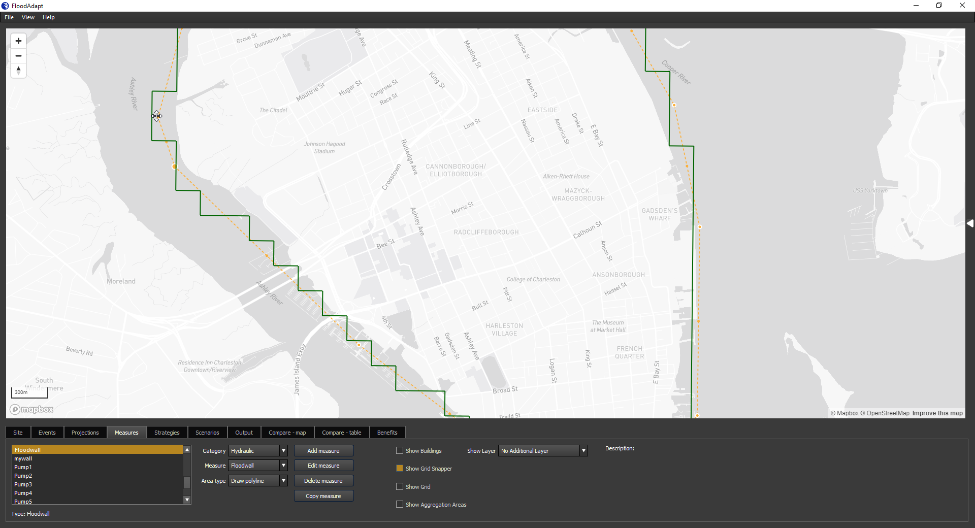
If you selected “Draw polyline”, you can now begin clicking within the map to draw a polyline where you want to implement your floodwall. When drawing the floodwall or levee, it is useful to turn on the “show grid” and “grid snapper” options so you are clear how your floodwall or levee will be implemented in the hydraulic model. We also recommend turning on the topography layer to ensure that your floodwall or levee ties into high ground, so that water does not flow around the edges of your floodwall or levee. Figure 3 shows an example of a polyline representing a floodwall without the grid, grid snapper, and topography visible. Figure 4 shows the same measure with these features enabled. You can see in Figure 4 how the wall will be implemented in the hydraulic model, and that the edges of the wall are tied into high ground.
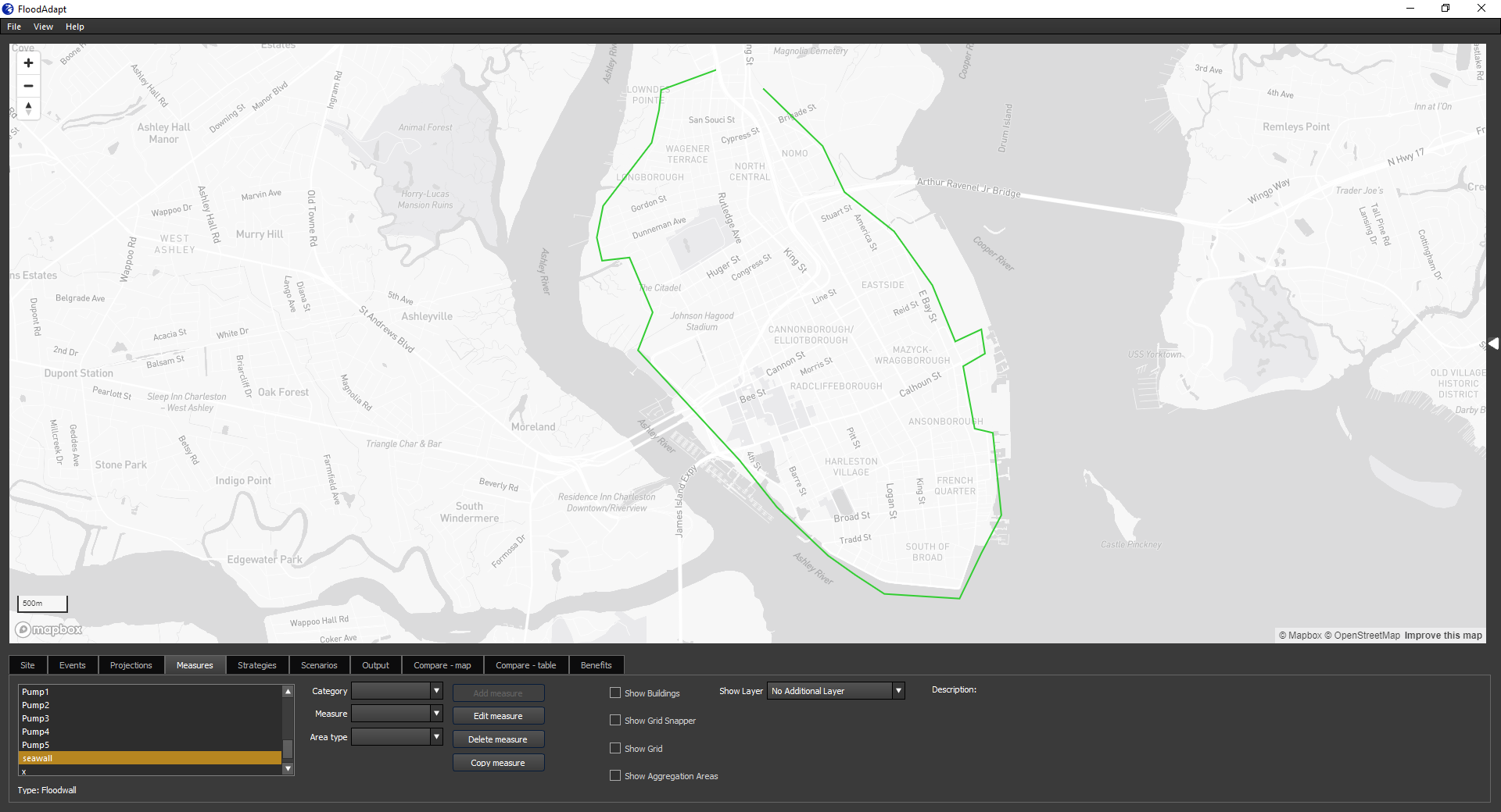

To turn on the topography layer, go to the top menu bar in FloodAdapt, click the “View” menu, and then from the drop-down menu click “Topography”. The topography layer will turn on. To turn the layer back off, again go to “View”, and again click “Topography” and the layer will disappear.
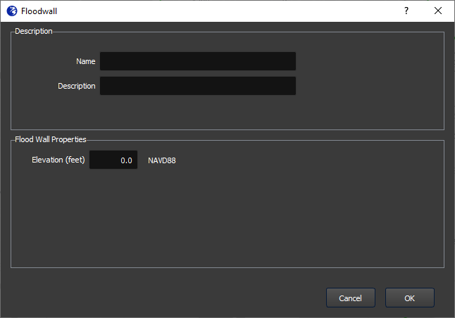
Once you have drawn your polyline or selected to import a polyline, a specification window opens (see Figure 5 for the example of a floodwall). In the specification window, the user enters a name for the measure (no spaces or special characters), an optional description, and the elevation of the floodwall or levee. Once you enter the information and click “OK”, your floodwall or levee will show up in the measures window.
Editing a floodwall or levee
Once you have created a floodwall or levee, you can edit it as long as you have not yet included it in a strategy. You can edit either the geometry or the parameters (the elevation) of the floodwall or levee.
Here are the steps to edit the geometry of a floodwall or levee:
- Select the measure in the “Measures” tab
- Click “Edit measure”
- A pop-up window appears asking if you want to edit the geometry or parameters; select “Geometry”
- The polyline is now ‘clickable’
- Click the orange dots to reshape the polyline. If you have the grid snapper shown, the snapped floodwall or levee will automatically update as you edit the polyline (see Figure 6)
- When you are finished editing the polyline, click anywhere else on the map
- A pop-up window asks you if you would like to keep the new geometry; click yes
- The geometry is now updated
Here are the steps to edit the parameters of a floodwall or levee:
- Select the measure in the “Measures” tab
- Click “Edit measure”
- A pop-up window appears asking if you want to edit the geometry or parameters; select “Parameters”
- The specification window opens
- You may change the description or the elevation of the floodwall or levee
- When you are finished, click “OK”
- The parameters are now updated
Pumps
Pumps remove water from low-lying areas or drainage systems to mitigate flooding. They are needed when gravity alone cannot allow for floodwaters to escape, or in combination with floodwalls which - without the inclusion of pumps - can trap rainwater within the area shielded by the floodwall. To implement floodwalls or levees in FloodAdapt:
- Go to the Measures tab
- Select “Hydraulic” for the Category
- From the Measure drop-down menu, Select “pump”
- Select one of the “Area type” options and then click “Add Measure”.
If you selected “Draw polyline”, you can now click on the map. While FloodAdapt allows you to click multiple points in your polyline, the only points that will be retained for a pump are the first and last point. The first point will be treated as the ‘intake’ location (where the water will enter the pump) and the last point will be treated as the ‘outtake’ location (where the water will be pumped to). When drawing pump intake/outtake points, it is useful to turn on the “show grid” option so you are sure your intake and outtake points do not fall within the same model grid cell. When you have finished clicking your intake/outtake points, double-click on the last point to open the specification window.
In the specification window, you enter a name for the measure (no spaces or special characters), an optional description, and the pump capacity. When you have finished you click “OK” and the pump will be added and visible from the Measures tab.
A pump in FloodAdapt is represented as a discharge between the intake and outtake points, using the discharge rate specified by the user when creating the measure. The discharge within the intake cell influences surrounding cells, causing water from these cells to drain into the intake cell as it is being discharged. However, this setup does not represent a pump connected to drainage infrastructure, and the effects of the pump are fairly localized to the intake location.